-
Santiagos 818R Build: The Voodoo Chile
Time to start my build thread! Wow, it really is time. My completion date was September 27th so Im waiting for Stewart to ship the new chile home. Delivery is set for this Saturday
As I look at the build threads that Ive followed, I feel a bit sheepish starting my own. So much helpful information has come through those early threads, so I dont want to repeat a bunch of stuff. Id much rather add info/tips that are not out there already.
Mine is not a single-donor build. Since Im doing an R-car and this is a pure race car, I didnt want to rely on too many used parts. Ill be doing some novel things in terms of suspension and safety, but the real emphasis is going to be on an extensive aero development program. Ill be using SolidWorks to do my CFD analysis first and then follow that up with instrumented field testing. So if youre interested in that sort of thing, hang with me. Hope along the way I can give back to this community which has already been so great to me. Ill share lots of information, but some of the more voodoo elements will remain proprietary.
A word on format. Im using the first seven reply spots for specific categories that will be edited along the way with up-to-date info. The rest of the thread will be business as usual with week-by-week work, how-tos, replies, etc. But these first few spots are reserved so that any interested party can just check out the first page of the thread and see the current set up and actual parts being used.
Last, this will be a long build, so I anticipate a lot of downtime in the thread. The early aero development is being done in stages, and my pockets are not so deep that I can source everything I want at once. Such is life.
Best,
-j
-
Suspension & Brakes
Brakes
These are the first parts to arrive! Ill be using STi gear, so that comes standard with Brembo brakes on all four corners. Id like lighter equipment, but for now itll work.
Suspension Gear
My main interest using the STi spindles & hubs was to get stronger bearings in front. Some folks think theyre overkill in the 818R application, but the way I figure it motorsports is overkill. So Im playing it conservative with overbuilt parts. I am also very happy not to have to press in the front bearings.
In front:
SPT Lower Control Arms (part # B2010FE251DS). Thanks to Chad Plavan for the heads up on this one.
STi Steering Linkage U-joint (2005 coupler shaft)
Sway Bar: nada even the mounts are getting cut off just as Rasmus did.
Out back: Theres no concession for NVH; its rod-ends everywhere. So:
VCP Wide Wheel Trailing Arms (Waynes the man)
VCP Track Pack Lateral Links (Waynes the man)
Prothane spindle bushings (ok, not a rod-end, but good enough)
-
Wheels & Tires
Wheels
The STi running gear pretty much solidified a 5x114.3 bolt pattern. Ill be using low offset wheels as part of the effort to increase track width, and preferably 17 diameter all around. The fenders are getting flared, so some of the common constraints many builders have previously noted wont apply. I have a pretty good idea what wheel Ill go with but Im still looking.
Tires
Tires will be slicks and only a tad wider than what FFR runs on their mules since Im a bit rule-constrained here. The car will be run in NASAs TT2 (time trial) & ST2 (wheel-to-wheel) classes. I like the ST group for its liberal rule set; very close to a straight power-to-weight classing system. However, there are a few modifications factors that influence classing, and tire type/size is one of them. So I have to look more closely at what Ill be allowed to run legally for a given amount of power.
-
Engine & Trans
(tentative)
• JDM ej207 (V7 or V8)
• JDM 6-speed transmission
I ordered the upgraded shifter from FFR, so we’ll see how that fares.
Last edited by Santiago; 10-15-2014 at 05:09 PM.
-
Exhaust, Fuel, & Electrical Systems
Electrical
ISIS Express Track Car Kit with Switch Panel: ordered and on the way. I have a track-buddy who will handle the rest of the wiring on the car. I dont do wiring.
Fuel
(tentative)
Harmon 12-gallon fuel cell (FIA-FT3 certified)
-
Cooling Systems
(Nothing yet
but this will be worth the wait
as any good aerodynamicist will tell you, this is part of the total package
)
-
Aero Development
What to Expect: Lots of cutting & body work. Not a single panel will go unaltered.
Perspective: Im building an aero-car, what Id call a medium-downforce car. Think: GT3-DTM love child. To me the current FFR mules are low-downforce cars, but theyre most definitely aero cars. Compare that to most track cars Ive seen; these are just standard sedan types with aero enhancements. They see usable downforce levels of only 10%-15% of their competition weight. The high-df cars are famous for generating upwards of (and over) 100% of their weight in downforce. Crazy. Thats not my plan. Ive got more pedestrian goals
somewhere in the middle.
From what Ive gleaned, the front of the car needs serious treatment. Its easy to slap a mondo-wing out back and generate way more downforce than what can be balanced by the front currently. So well start in front (in theory). Actually, Im starting with basic studies on a full underbody tray, but results are not in yet. Voodoo takes time.
-
Senior Member

Santiago, Good to see your build thread started.
Fast Cars, Fast Women, Fast Haircuts!
-
Senior Member

This will become a very interesting read.
-
Senior Member

Very cool Santiago, I think your CFD work will help many of us get a better handle on the air flow around the car and help with intercooler placement. I've done some CFD work in the past using fluent and floEFD and I know some of those solutions can take quite a while to run. Does solid works use their own CFD package or are you just using that to generate the CAD geometry?
-
Solid Works has its own fully integrated CFD package. It's pretty damn impressive. I think there's a lot for us to learn from it.
As good as it is though, I'm not using it to predict absolute values. Rather I find it more useful to check the feasibility of applying known aero-solutions to our platform as well as identifying trends in the aero effects of new part designs & integration. The real-world values will be taken from the real-world testing (props to my airplane pilot buddy whose sourcing abandoned airstrips for me). Sadly, we're a long way from that stage.
Best,
-j
-
-
-
Tazio Nuvolari wannabe

Congrats. I expect lots of good ideas to come out of this build thread!
-
-
-
Post Thanks / Like - 0 Thanks, 1 Likes
-
Do you trim off the extra length of thread after you’re happy with the fit? I agree with your logic, just wondering what the cost for hardware would be following your method. My opinion regarding bolts, etc used on these cars is this; some metric, some U S, some sheet metal screws, and the like. It would drive me back to drinking to try and use only metric. Lots of things I’ve bought have been compatible with American bolts. Changing would entail work that, quite frankly, wouldn’t enhance the quality of the car, IMO. Many places, only grade 2 bolts will suffice. If you consider the stress involved only a few bolts will be critical. Also, I don’t ever use fine threaded fasteners in aluminum. It’s good advice, tho to do it your way unless you have some engineering background to assess the forces subjected to the part.
-

Originally Posted by
lance corsi

Do you trim off the extra length of thread after you’re happy with the fit?
Hey Lance, when you use AN/MS hardware you need to measure the grip length. Pick the bolt that is sized for that, and you don't have to cut any thread - you really couldn't cut much thread off anyway. They're designed to have only enough thread to match the grip length + a standard AN washer (which are 1/16" thick) with about three threads protruding. Since actual grip length on whatever you're working on rarely cooperates precisely with that, you can use thin AN washers (1/32" thick) or extra thick ones (typically 1/8") to dial in your grip length.
In a pinch you could use a standard grade 8 bolt with long shoulder and cut the unwanted threads off of that. More work, but feasible. I've found the lengths of those shoulders rarely match the grip length of whatever I'm working on (did it once, but it wasn't this project). Easier to take time to measure and then source the right AN bolt.
I hear you on the mix-and-match challenge. I would prefer all bolts to be of one unit, but good lord that would take a lot more work. The bolts I put thought into are really only the primary suspension ones - anything that's going to be repeatedly loaded in shear (or has the potential to nibble into softer material) catches my attention. All AN/MS hardware are in English units, but they're all fine-thread (which is stronger in shear and less prone to loosen in heavy vibration environments).
Cost can rise rapidly if you order what you need when you need it. I mean - rapidly; like when you have to replace that control arm bolt on your wife's Camry and the dealer charges $15 for just one flippin' bolt, argh!, (incidentally, not surprising that those bolts the OEM's use are designed the same way - grip length dictates proper bolts when loaded in shear). But I'm an avid yard-sale shopper for hardware, always poking around for who's got what in common lengths I've encountered. Buying in bulk is the way to go, most of what I've picked up hasn't cost much more than what the local big-box stores charge for grade 8 hardware. I just picked up a collection of camloc hardware that would have run over $150 off an ebay seller who clearly didn't know what he had - got it for $27 shipped. Only fussing over the suspension bolts is another way to keep costs down.
Agreed on fine-thread in aluminum, big no-no. Then again, there's not much aluminum on the car that you would use as a parent material - I hate sheet metal screws with a passion. The aircraft guys have this nailed down though, plenty of hardware options for properly fastening aluminum sheet, the real decision is how fast/easy do you want to be able to remove it: structural adhesive, rivet, pem, rivnut, nut plates, Dzus/camloc. The tools/time you have on hand for installation make a big difference too.
Obviously...5 years later, I've got some time. 
-
i know where you are coming from with a 3-4 or more year break. Honetly i'm guilty too. I have got a ton of work done with mine since my actual start. I can't wait to see the things you come up with once you really get back to it
-
Originally Posted by
Newkitguy
i know where you are coming from with a 3-4 or more year break. Honestly i'm guilty too. I have got a ton of work done with mine since my actual start.
We should form a support group... =)
"Hi, my name is John, and I'm a slow builder..."
-
Post Thanks / Like - 0 Thanks, 1 Likes
-
Senior Member
You may find this helpful regarding which fasteners to get although it sounds like you've already got a handle on it:
https://thefactoryfiveforum.com/show...l=1#post221711
-
I completely agree with you on using AN bolts for suspension pivots and such. Basically any critical bolt that is not in just tension. I've read most of Carrol Smiths books and agree with him on that.
I'm also part of the 4+ year build club ��
Haven't done much on mine in the last year, but making a push to get it on the track by summer. Thanks for updating your thread, gives me motivation.
-
In My Off-Time
The years (*cringe*) between initial purchase and now havent been entirely unproductive. Since my whole build has always been to serve as a platform for my aero interests (a laboratory test-bed of sorts), I knew I would be substantially redesigning the body.
Since the body needs to fit on the chassis, I made this in SolidWorks:
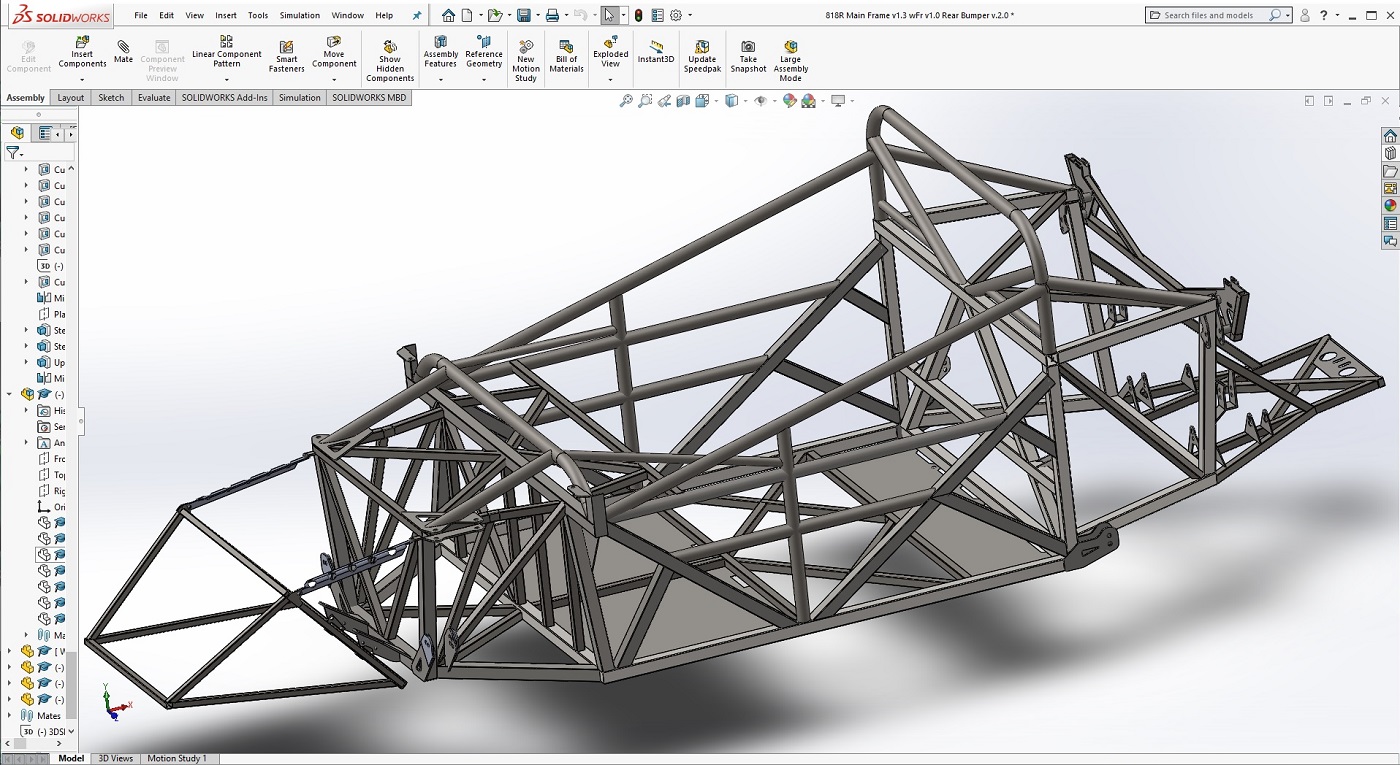
This little sucker has proven very useful in working out different ideas its a heck of a lot easier to position, rotate, and play with clearances on something like my intercooler in its digital guise than to wrestle with the real one. Ive also been working through different bumper designs, wing stanchion supports, and other modifications in this digital environment.
If you look real close, you can already see small changes in this digital model over the standard chassis as it is supplied by FFR
kind of like playing a game of Wheres Waldo? Who can find all the modifications? (HINT: There are at least four you can see in this image)
Being able to run FEA and CFD tests is also none-too-small of an advantage. =)
-
Senior Member

Originally Posted by
Santiago
If you look real close, you can already see small changes in this digital model over the standard chassis as it is supplied by FFR
kind of like playing a game of Wheres Waldo? Who can find all the modifications? (HINT: There are at least four you can see in this image)
Being able to run FEA and CFD tests is also none-too-small of an advantage. =)
I see the following four:
- The rear X section were the trans sits has been shortened
- The ears for the front sway bar removed
- The windshield / door mounts removed
- The front lower control arm mount closest to the firewall removed
Is the at it?
-
Tazio Nuvolari wannabe
Originally Posted by
Hobby Racer
I see the following four:
- The rear X section were the trans sits has been shortened
- The ears for the front sway bar removed
- The windshield / door mounts removed
- The front lower control arm mount closest to the firewall removed
Is the at it?
I've done all but one.
John, we should collaborate. I've done an S2K front spindle setup with fully adjustable double wishbone suspension. Stoptech brake system was spec'd by their engineers. Floor mount Tilton pedal system mostly done.
I'm thinking undermount turbo and DS. Just got the DS.
I have GTR twin intercooler system radiators to adapt for turbo intercooler.
-
Originally Posted by
Hobby Racer
I see the following four:
- The windshield / door mounts removed
Item 3. How much of this can you remove for the "r" version?
IMG_8363.jpg
-
Senior Member
Originally Posted by
Blu
Item 3. How much of this can you remove for the "r" version?
IMG_8363.jpg
I removed the entire bottom section. You need the two top upside down "L" shaped parts to support the front fender and the hood pins.
I can post a pic later if you need one.
-
Post Thanks / Like - 1 Thanks, 0 Likes
 Blu
Blu thanked for this post
-
Originally Posted by
Hobby Racer
I removed the entire bottom section. You need the two top upside down "L" shaped parts to support the front fender and the hood pins.
I can post a pic later if you need one.
Ah yes...if you were using those fenders I suppose you would need them... ")
Hood pins are getting relocated - hood is getting hacked up and the current pin location is too far outboard.
I removed most of the bottom section - I have a suspicion that the hole and slot on the top half of that bracket will come in handy later. If not, it'll get cut too.
-
Senior Member
OMG that would be so helpful... I have modeled up a few section when I did my headers but never had the time to do the entire chassis.
If it would be possible could I get that file! PM me and I'll give you my email.
-
Son-of-a-gun! I totally forgot about the firewall control arm mount. I never added that because it was one of those things I was going to get around to but never did. Argh...makes me want to go in and edit...
So there's still two more...one is related to the front control arm... I'm not going whole-hog like Scargo, but there's a teaser up front of a little sumptin'-sumptin' I'm doing.
Hobby, I'm happy to share. There are some very minor discrepancies in the model (mostly with strange tube orientations on some of the smaller 1" diagonal bars - their location is pretty close, it's just the profile orientation that was odd). And I have some reservations on the precision of the angle that the steering rack mount is set here. These didn't have anything to do with my plans, so I haven't bothered to touch them up. I'll PM you with some more details.
-
If you are willing to share, I would love to get on it as well. I'm actually taking an udemy.com course on fusion 360 now so that I could model custom body parts, hopefully to be cut in foam on a CNC. My Primary goals are a new front bumper and and a truly removable hardtop for the S (not a conversion like the 818 offering). Having the frame would certainly save a ton of hours, although I'm sure I'll have to make a fair amounts of updates for the S versus the R. I'll be happy to share with anyone else the cad files I come up with.
-
PM's replied to.
Ajzride, shoot me an email address.
Best,
-j
-
Steering Quill Mods
I followed suit with others who have modified their power steering quills to take out that little slop from the internal tension bar. I welded mine solid rather than try to fill the fluid passages with epoxy. Just a quick heads up for anyone looking to do the same.
This turned out to be pretty easy. The trick is freeing up the ball bearings before welding. The internal cage is plastic, so there was some concern that the heat of welding would damage it if left in place. Fortunately, a little fiddling with a pick makes quick work of it, as it pops right out.
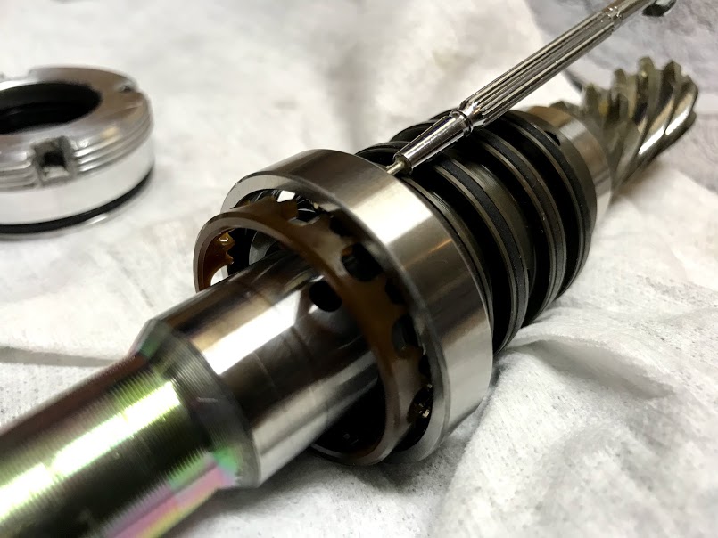
Then everything comes out easily:

Now welding is cake work, and reassembly is the reverse well, you do have to be pretty patient getting everything back together without the ball bearings falling out before you line up the race. You have to stack all the balls at the bottom, hope they stay in place long enough for you to rock the outer ring back in place. Took me about a half dozen tries or so. Once you get it, the cage pops back into place.
-
Quick Release Steering Wheel
I am using a Woodward QRA-1 quick release. Very nice unit, very tight/no slop, easy to use. The basic idea is to simply weld-on the Woodward splined stub to the OEM steering shaft. I struggled a bit with figuring out how to get everything lined up, and I didnt want to overheat the bearing on the end of the column. Then I realized that Subaru figured it out a long time ago.
The stock steering wheel has aluminum spokes, but the internal hub is steel. That little hub is both splined to match the stock column and tapered to match it as well a perfect fit. Getting it out requires persistence
and a 20-ton press. Mmmm
the steering wheel does not survive surgery.
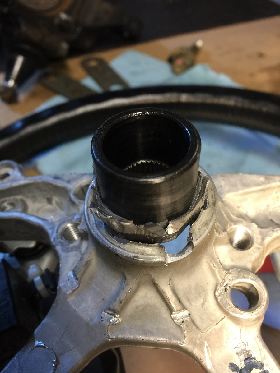
After a little mutilation of the stock wheel, I got a nice hub to use.

Slid the splined end on and snugged it up with the steering wheel nut. Now you don't have to weld close to the bearing, you just weld the nut to the OEM spline to the Woodward spline. Once everything is welded together, nothing moves and I have an adapted OEM column to match my quick release. Heres the layout:

And heres wheel option #1 mocked up.

I wanted a clear view of the data logger, so Im going with an open top steering wheel. Ill see how that goes. Right now it feels fantastic, but Ive got a larger Sparco D-rim in the wings if this one turns out to be too small in action. For now, Im totally digging it.
-
Post Thanks / Like - 0 Thanks, 4 Likes
-
Harness Bar and Seat Mounting
I managed to get my seats mounted low like really low without cutting the X-bars. The formula for me was:
- Use a layback seat (18 deg in my case) the popular composite ones are typically very upright (like 10 deg if youre lucky), making them quite tall
- Make your own mounting base angled at 10 deg
- Be short Im 5 7 and not disproportionately long in either torso nor legs, so I can afford a bit more loss of leg room than some
The net result of all this is that the top of my head sits under the line where the forward down bars meet the main roll hoop. Even with helmet on, I easily pass the broomstick test. Top of my head is a bit below the level thats clamped in place here.

My seat base:
The downside to this is that my shoulders are so low I had to make a custom harness bar. Like many others, I realized that the little bar between the main hoop and diagonal bar that FFR supplied is not suitable for anything but a very tall OEM seat. So my original plan was to follow Rasmus lead and use the top bar of the rear bulkhead. But even with my head-and-neck restraint on, the webbing was still at a positive angle.
I wanted my shoulder belts to fall at an angle below 0 (i.e. dropping down as they come off the shoulders). An angle of 0 to -20 deg is the industry standard (and what will pass my chief tech inspectors watchful eye), so thats the range I wanted.
For the record, I just cant understand why FFR bothered to put in that silly sub-belt mount. I cant find a single authority on belts that accepts that as a sub-belt mounting location (well, theres a rally organization in South Africa that looks like they may accept it...so I guess if you live in South Africa
yeah). At any rate, stuff like that would never pass tech with my organization (NASA), and I dont know of any other competition organizations who would pass it either. This is pretty old-hat and FFR has been around long enough to know better. 
*deep breath*
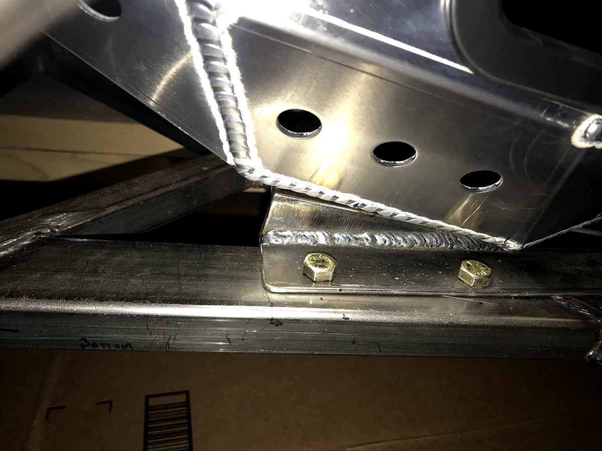
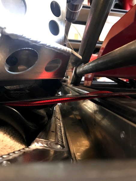
My belts are not perfect, but I did make some effort to get my harness bar at the right height so the shoulder belts were close to the ideal ranges/angles. I welded in some mounting tabs and used the top of the bulkhead triangle to bolt it in the center. Four bolts in total hold it in two 5/8 bolts on the ends (through the rod-ends), and two 3/8 bolts in the center.
I had this old panhard bar lying around that proved ideal for the job. I welded on a couple of tabs to it to secure the back of the seats; now it plays double duty of being the top seat mount as well as the harness bar. Wallah! harness bar fits well.

I love a seat that feels like an extension of the chassis it does not move, super solid, super communicative. Talk to me sweetheart, I need to know what you need so daddy can deliver
-
Post Thanks / Like - 1 Thanks, 4 Likes
-
Wing Mount Design FEA
Since were on our own with developing our wing mounts for the 818, I thought Id share some of my development work. The first iteration of my design showed how BAD my thinking was on this
=) Fortunately, I have yall to blaze trails and offer insight.
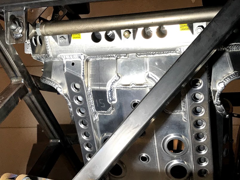
From early on, knew I wanted a few things out of my wing mount sub-frame: (a) a swan-neck stanchions (b) in double-shear, (c) setting the wing back past the deck. I also knew this meant placing quite a moment through the wing stanchions and into the mounting sub-frame. So I committed to a rectangular 4-bolt pattern to secure the stanchions rather than the typical pair of bolts in a single line. That set the stage. Five iterations later, along with a couple humorous FEA failures, and I was pretty happy.
Then HobbyRacer came along. I LOVE his wing mount sub-frame. My 5th major iteration had some similarities with it, but his was so much more elegant. So I copied it. Ok-ok, I changed it a little by adapting it to my 4-bolt hole pattern, made some tweaks here and there, and added two more legs. Thus v.6.0 was born.
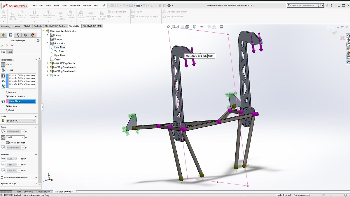
At the same time, I was refining a generic swan-neck wing stanchion design. By the 2nd major iteration, I was close to what I wanted, so I set up the new assembly for tests:
Early FEA results were pretty promising the Hobby-inspired stanchion was doing better than my 5th iteration, and by v.6.4 I thought I was close to finalizing the design.
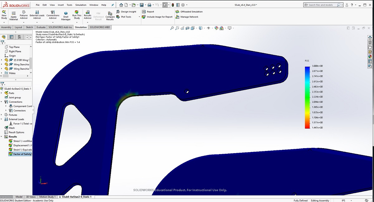
All the tests were done using the maximum downforce generated by the wing (1,600 lbs. according to the CFD data supplied by the manufacturer) at a theoretical top speed of 200 mph. Of course, my car isnt really ever going to go that fast, so it wouldnt see that level of downforce. And frankly I think the CFD data is
shall we say, on the optimistic side. Still, I figured I might as well go for it (throwing in a modest 50 lbs. of drag for good measure). For this sort of an overloaded scenario, a Factor of Safety (FOS) above 2.0 wouldve made me happy. Heres what I got in the v.6.4 test:
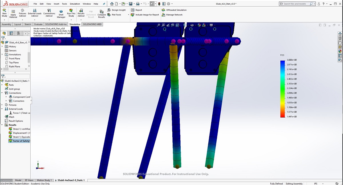
As you can see, the tops of the rear legs and the horizontal bars holding the mounting plates were pretty marginal and/or below my goals
and these were the improved versions. So I knew I needed to give this area more attention.
At the same time, the throat of my swan-neck stanchion was showing a small area of concern.
Some design changes were needed.
-
Post Thanks / Like - 0 Thanks, 2 Likes
-
Senior Member
Originally Posted by
Santiago
Then HobbyRacer came along. I LOVE his wing mount sub-frame.
Hey, thanks for the shout out. Glad I could inspire you. Your design is excellent. Many more hours of thought and actual engineering than I put into my design. 
-
Improving Wing Mount Sub-Frame and Stanchion
For the swan-neck, I figured I could take the chamfer out of the marginal area along the throat of the stanchion. I also increased the radius of it. Last, I shortened the stanchion 2 and thinned out the neck overall. So the iterations of v.3.0 were developed, lighter but stronger yet.
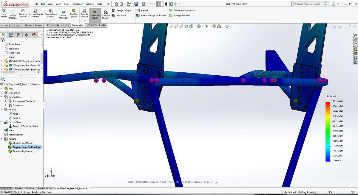
I was going to add a simple gusset to the troubled horizontal bars when I realized that a redesign might be worth looking into. So v.7.0 was born by taking out the forward legs and using them to tie the wing mount plates directly to the rest of the top perimeter bars. Like this:

FEA results on that set up were a huge surprise! First, taking the two legs out did make it a bit lighter than before, but also stronger overall by completely transforming how the sub-frame works.
This design spreads the load over a much wider range of the bars. Now the entire top perimeter is able to heave upward as the stanchions place the force of their moment on the sub-frame. This is easy to see in the displacement graphic here (note: SolidWorks exaggerates the displacement so its easy to visualize, but the actual displacement is quite small, approx. 1.5mm maximum):
It's clear that the forward legs in the previous design were acting in tension to keep the mid-section of the upper perimeter tied down (i.e. reduce the heave). However, this made the stress on the vertical arms quite concentrated in that old 4-legged design. You can see this most readily in the displacement graphic to v.6.3:

Surprisingly, taking away those two legs made the entire assembly work in greater unison. More bars are working, but everyone is still happy:
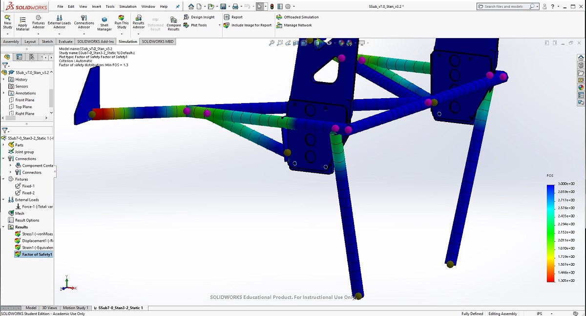
Of course, what immediately pops is an entirely new area of concern. I never had a worry that the forward mounting point might get overworked. With the top perimeter heaving more than ever before, the joint at the front was under large stress (see the red spots indicating a FOS below 1).
Everywhere else the FOS was improved and exceeded my target. The stanchion throats were also looking better.
Last tweaks to the design (v.7.1 of the sub-frame and v.3.3 of the stanchion) resolved the remaining concerns. I added a couple of small gussets to the forward joint, and then increased the radius of the stanchion throat even more.

The current result has a FOS around 2.0 or more for everything. Very small tweaks from here, but Im satisfied with that.
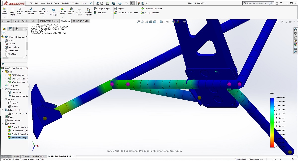

All told (23 hrs later), I feel good-and-ready to start cutting. =)
-
Post Thanks / Like - 0 Thanks, 4 Likes
-

Yes, I love Technology

Thanks for showing the process. I have a wing in mind but it is a showboat piece, not a functional item. Still very interested and enjoying your design/analysis work.
-
Nice work! I do all my design in SW as well. For the adjustable wing angle mounting pattern, do all the holes line up or does the wing have one hole and then a slot?
Last edited by Mechie3; 02-10-2020 at 04:06 PM.


 Thanks:
  Likes:


 Reply With Quote


