-
-
White makes it easier to spot leaks.
"Good Judgement comes from Experience. Experience comes from Bad Judgement"
Owner: Colonel Red Racing
eBAy Store:
http://stores.ebay.com/colonelredracing
818R ICSCC SPM
Palatov DP4 - ICSCC Sports Racer
-
Current plans are for a copper body with CF accents and fairing the roll-over hoop. So little of it will show on the outside; the cabin door bars will probably be the most visible tubes apart from my rear bumper. I was thinking of something that (a) compliments copper and (b) contrasts with the aluminum paneling.
I totally get the drive towards lighter colors...functional...but this may be one of those concessions I make to aesthetics (some seriously sexy charcoal greys out there  ). We'll see. This Tuesday is drop-off day; I'll make the final call then.
-
Post Thanks / Like - 0 Thanks, 1 Likes
-
Senior Member


Originally Posted by
Santiago

Current plans are for a copper body with CF accents and fairing the roll-over hoop.
You just described my car! 
You have excellent taste.
-
Originally Posted by
Hobby Racer
You just described my car!
This is true. And your car is stunning! But this time I'm not just playing the toady and copying you (as I am often want to do). =)
These are the same/similar colors that I did my last race car. At one point I thought of keeping the RX-8 and finishing this build so I could bring cars with "team colors" on them. Sold the RX-8, but still love this color scheme. Seeing it on your car validated my thoughts on how it would look - just fantastic.
-
Senior Member
Some day I would love to get a bunch of us with 818's together at a track. It would be a lot of fun, and make for some great pictures!
-
Post Thanks / Like - 0 Thanks, 2 Likes
-
Interim Engine Prep
Time again to catch up with the build.
While the chassis was out for powder coating, I’ve kept busy with some minor engine prep, getting it ready for the dry-sump install. Mostly I’ve been researching that install, watched (over and over again) half-a-dozen "how to" videos on pressing in rear bearings, and back-reading what can be deleted from the OEM engine systems (evap system, coolant bypasses, etc.). New spark plugs went in too (BKR7EIX).
First up, clean some ugly looking aluminum brackets (alternator and AC pump brackets).

I decided to try out Sharkhide metal protectant. So far, I’m liking this stuff. It’s very easy to apply, and if it protects anywhere near as well as it’s supposed to it should be great. I’m putting it on just about everything I come across.
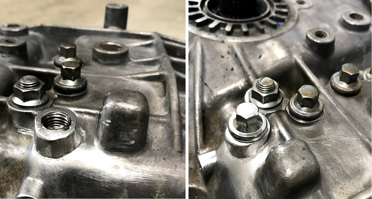
I removed the OEM oil cooler, because…well it’s pretty ugly and I'll have an oil cooler plumbed into the dry sump lines. That makes it unnecessary, only adding extra points to leak. So I took it out and ordered the non-turbo oil filter fitting (part# 15018AA090). I didn’t order the right plug to replace the coolant return fitting that no longer has a function. So I cut the nipple off the existing fitting, inserted a 3/8” dia steel slug and welded it shut.

Without this cooling circuit, I ditched the hose from the water pump. I ordered a new pump (part# 21111AA026), but I should have ordered a different one (the one without the fitting pressed in the side). Fortunately, I had notes from Scargo on how to press this fitting out. Tapped ¼-NPT threads into the existing hole w/o even needing to drill it out, per Scargo's notes. Plugged it, done. Easy.
I got around to doing Wayne’s coolant mod as well – must have been in a tapping mood. I’ll run a 5/16” line to the coolant overflow tank.
Speaking of cooling mods, figured I’d try out the cylinder #4 cooling mod. I ordered a Getadomtune kit and a 90deg silicone elbow. You don’t really need the elbow (black silicone), but without the lines to and from the heat exchanger in place to tap into, the elbow made the install a bit cleaner.

There’s more engine prep to do before it goes back in the chassis:
- Install new timing chain & water pump
- Gut the oil pump
The chassis is back though, so I’ve been getting the suspension bits ready to install so I can finally have a roller.
Up next: New wheel bearings.
Last edited by Santiago; 02-04-2021 at 02:53 PM.
Reason: better pic
-
Post Thanks / Like - 0 Thanks, 1 Likes
-
Tazio Nuvolari wannabe

Nice! I think that plug is the same as what goes where you access the piston pins.
Be sure and use a high temp wheel bearing grease. What a pain to remove grease in wheel bearings and replace. You may know all this but this is what was easiest for me. Plugged the bearing's hole, fill glove, clamp, squeeze.
IMG_2629.JPG
Looking forward to it coming together!
-
Wheel Bearing / Suspension Prep
Getting ready to make a roller! How many years has it been? =O
I did the basics: new wheel bearings front and rear, new Prothane bushing to receive the rear lower trailing arm, new ARP wheel studs (long), and cleaned what little OEM hardware I will reuse. While I was at it, I wire-wheeled everything down and put a coat of paint on the rear stuff.
I also cut off the rear dust shield (noticed they did this in the manual as well). Hideous awful looking things anyway. They are held on by about 8 spot welds:

Overall, Im quite happy with how everything came out. Looks better than brand new:


Since Im using STi gear the front wheel hubs just bolt in with bearings included as God intended! Why were still using press-in bearings at the rear
argh! This was my first time I ever pressed in wheel bearings. It went fine, but what a waste of time compared to the fronts. The fronts were like, boom, bang, bing; youre in, youre out, youre done.
The front uprights went to powder. Not entirely happy with the color choice I thought it would be lighter/more silvery, a closer match to the lower aluminum arms, but its fine. I decided to Sharkhide the hubs, so well see how they do. Pretty (for now):

One curiosity: I was on the fence with whether or not to trim down the front CV stub. Others have done it, you see it in some of the pics in the manual, but I wasnt sure if I should take the time. I went with it:

WOW! Im so glad I did this. First, I shaved almost 2 lbs of rotating unsprung weight on each side. Second, they look so much better this way.

On the front LCAs, I took a page out of our 818R grand-daddys playbook, Chad Plavan, and went with new SPT front control arms. Stiffer bushings and a new ball joint sold. After a couple years on the shelf (
*ahem*
), they still looked pretty good. 15min later with a stainless wool pad, quick coat of Sharkhide, and wallah:

Lately Ive been working through the small spacers for shocks, etc., and fabricating the bump-steer set up. Almost done there.
Next Up: A Rolling Chassis
-
Post Thanks / Like - 0 Thanks, 6 Likes
-
Tazio Nuvolari wannabe
You might consider going further.
818 brakes-1.jpg
Looking good!
Mine sits.
BTW, I have a tranny that you or someone might be interested in. A 5MT, newly built hardened STI RA Gearset, 2004 Subaru WRX Transmission. Built by Rallispec, it contains STI RA Gearset 1-4, heat treated stock 5th Gear, new, OEM synchronizers and bearings and a Cusco 1.5 LSD. There was approximately $5000 invested in it and it has the rear plate installed for the 818 kit.
Last edited by Scargo; 02-14-2021 at 07:00 AM.
-
Originally Posted by
Scargo
I did consider that...should have hit you up before putting everything back together. So my concern was strength. Have you (or folks you know) cut down the rear caliper mounts that much and used them on track?
Honestly, I would have loved to do it but just wasn't sure about the structural situation I'd be getting into. Any thoughts/considerations welcome.
I may be in the market for another trans (low probability), but shoot me a pm all the same. Open options are good. 
-
-
Post Thanks / Like - 0 Thanks, 4 Likes
-
-
Post Thanks / Like - 0 Thanks, 4 Likes
-

Yes, I love Technology

You should be excited, if not, then you are not in the right line of fun with this project. I know the feeling and sometimes it is the simplest of things that get you there. Cool solution for that bushing.
-
Senior Member

You deserve to feel excited about that accomplishment. I feel so sorry for guys who just sign a check, or worse, a loan agreement for a car and have no idea that they are missing the hundreds of satisfying accomplishments in building their own ride.
818S/C : Chassis #25 with 06 WRX 2.5 turbo, ABS, cruise, PS, A/C, Apple CarPlay, rear camera, power windows & locks, leather & other complexities. Sold 10/19 with 5,800 miles.
Mk3 Roadster #6228 4.6L, T45, IRS, PS, PB, ABS, Cruise, Koni's, 17" Halibrands, red w/ silver - 9K miles then sold @ Barrett-Jackson Jan 2011 (got back cash spent).
-
Post Thanks / Like - 0 Thanks, 1 Likes
-
Chassis Aluminum
Aluminum is done
and Im exhausted. For the love of Pete, that was waaaay more work than I thought it would be.
I dont know about yall, but if I dont have to touch my drill for another month or two

Contributing to the workload was a bit of fabricating for the following:

Engine Bay Bulkhead (3 pieces)

Door Anti-intrusion Panels (2 pieces)
There were also a slew of other modified or scratch-fabricated cabin panels (like the upper cabin block-off panels). I think only two panels were installed as shipped from FFR. The rest were massaged and adapted to my build.
Some info-tidbits:
ALUMINUM DOOR PANELS: These are pretty close to what Plavan put on his car. They are cut from 1/8 thick 7075-T6 sheets (Chad used T7 temper, which is a bit nicer insofar as its elongation % at break is a bit higher
but I got a screaming deal on the T6 sheets, so theres that). This 7075 stuff is unreal. Whatever FFR used for the cabin bulkhead in front of the fuel tank is like butter by comparison. That stuff is soft and easy to drill; you know, almost like its made of aluminum. The 7075 is not as tough to drill as steel, but its way harder than most aluminum Ive used before. 14 lbs ea., for those keeping track.
ENGINE BAY BULKHEAD: These are made of the same 7075-T6 sheet (I told you I got a good deal on these). I managed to get the whole rear covered with just three panels (one across the top, two along the bottom). Then I covered it in heat reflective sheet. Before the sheet went on, you could see the access door opening to run the fuel filler and other hoses. Ill drill out access holes for electrical when the time comes.

CABIN SEALING: The supplied panels dont really seal the upper portion of the forward bulkhead in the 818R chassis, at least not in a way I was going to be happy with it. So I used the 0.040 aluminum panels that were originally meant for the doors and cut three pieces: a middle and two sides. The sides are cool. =)
I wanted the cabin sealed off from the frunk area where Im mounting my oil tank for the dry-sump. Mostly Im trying to be rules compliant. NASA regs state that any oil lines that go inside the cabin must be shielded or of stainless braid. Mine are not stainless, theyre aramid. So I made some block-off panels that will allow me to run the return line along the outside of the door panel and then into the frunk all without having to go around the front of the cabin chassis bars (driver side will be used for master cut-off switch cables). The top of these panels will be covered with bulb-seal and then flush to the bottom of the dash Im making. Now Im rules compliant. Double-bonus round: with these as well as the mods made to the lower corner panels, Ive preserved the clean lines of the forward chassis bars
because
[shhh
its in the voodoo-aero
].

To RIVET or NOT to RIVET: The front cabin panel that houses the steering wheel column is not riveted yet waiting until after I position the column and drill the hole. The fuel cell will be serviced by removing the cabin-side bulkhead. So I didnt use rivets there. I used nutserts for M6 bolts. The two halves are also not yet riveted (theyre Clecod), because Im not sure how much of a pain the wiring will be with a full panel in and out of the car. Love me some Cleco clamps.

"Heres looking at you kid!"

Next Up: Trans R&R! (Im in over my head and loving it.)
-
Post Thanks / Like - 0 Thanks, 2 Likes
-
I have 5 x 114 wheel hub envy. That opens up the wheel options a lot. What size tires are those on the front?
"Good Judgement comes from Experience. Experience comes from Bad Judgement"
Owner: Colonel Red Racing
eBAy Store:
http://stores.ebay.com/colonelredracing
818R ICSCC SPM
Palatov DP4 - ICSCC Sports Racer
-
Originally Posted by
Sgt.Gator
I have 5 x 114 wheel hub envy. That opens up the wheel options a lot. What size tires are those on the front?
Yeah, the 5 x 114 pattern was a major factor in my decision to go with the STi running gear.
Front tires are currently 245/620-17 Pirelli slicks on a 9" rim.
To me, Pirelli slicks always seem to run on the small size, but that may just be because Hoosier always seems to cheat... =)
-
Adventures in Aluminum
Aluminum. What to say? Were not on good terms, but our therapist says were making progress.
My JDM trans arrived months ago damaged. *grrrrr* Dealing with the importer was a joke, so I wont go into it. At some point I figured either I was going to fix this thing or get a new trans. The damage wasnt particularly bad, but it was frustrating.
The bolt that holds the lowest shift detent ball & spring was missing (along with the ball and detent spring). This was probably because the boss that the bolt screws into was missing
Ok, it wasnt all gone, but it was half gone and the remaining threads were partially stripped. Like this:

What to do?
Option A involved a credit card.
Option B involved a smaller credit card (new case halves)
Option C involved old age and treachery
I must be getting old, so I decided to fix this thing. I had a basic idea of how I was going to go about it, but no real experience. The plan was to rebuild the boss to support new threads.
Option C-1 involved JB Weld (`cause
well its JB Weld, so its easy)
Option C-2 involved that aluma-weld brazing rod stuff
Option C-3 involved welding around a stainless bolt saw this on You-B-Tubie, so its gotta work!
Someone on the Tube did a test of the torque range of JB Welded threads. I wasnt liking what I was seeing despite the fact that this bolt isnt heavily stressed nor heavily torqued.
Many moons ago I picked up a smoking deal on a pack of aluminum brazing rods a great deal from a popular social media site. And that should be all I need to say, but you gotta check out the results.
To my mind, the concept of any form of brazing (and yes I know about brass/copper and how this is aluminum, blah-blah-blah; so stuff it, were talking about aluminum brazing anyway), the core concept is that you are using a rod material with a lower melting temp than the parent materials you are sticking together. Thats the concept.
This is what happened:

I was literally able to melt a 3/16 thick cast aluminum casing with a MAPP torch
before this stupid 1/16 thick rod came close to melting!! As soft and flexible as this rod is, it just pushed in a deep groove in the melted cast aluminum. Hows that for quality parts purchased off your favorite social media site
Would you believe I actually did multiple tests with this stuff, trying different techniques, scraping away its surface layers, etc. Im sure the name-brand stuff purchased from a reputable supplier is great. But that is not what I had on hand.
Time to try that other genius idea of using stainless bolt as a form around which you can lay down molten aluminum. I still had this transmission tail case lying around that would make a perfect practice piece to refine my awe-inspiring skills. I like it!
Total. Fail.
Heres the thing: welding aluminum like this is all about heat management. That makes a TIG machine invaluable its like a rheostat for heat input. But I have a MIG welder. Granted, I do have a spool gun, but its still akin to using a hammer-and-tong to scratch behind your cats ears.
With very little heat management on hand I found out some interesting things. Like for example, you CAN melt stainless steel with a spool gun set up for aluminum. Mmm-hmm. And here I thought stainless had such a higher melting temp. Turns out, it does melt at a higher temp, but temp build-up is also a function of mass. So when those tiny little ends of the threads are exposed to a sudden and brutal onset of heat they melt right into the aluminum. Who would have thought?
Physics

I tried a bunch of pre-heating with a torch and finally got a stainless bolt to work
sort of (it was pretty ugly, I dont wanna talk about it). Moving along.
Option C-3b involved more trickery (because were older by this point in the story, and rapidly getting more crafty)
Remember that JB Weld? Relax, I didnt use it. However, I did think of it as a benchmark. Anything better than that would be success. So I had this idea to use a Helicoil as a sort of sacrificial heat barrier. [Side Note: the interim Option C-3a idea was to use a Helicoil and pack in the backside with a bunch of JB Weld to rebuild the mass of the boss, because we were getting desperate at this point.]
The idea was simple: if the MIG is apt to melt the tips of the threads, let them! Melt the outside threads of the Helicoil right into the built-up aluminum being fused to the boss. The inside threads would still be intact and ready to take up the bolt. Working with my trusty practice trans tail end, I was floored at how well it worked. I even tried replicating the damaged side and rebuilding the mass of the boss. Little bit of pre-heat with the torch on the base metal and pausing once I saw the Helicoil getting red hot. The key is to keep your passes on the aluminum and just let it flow towards the insert.
Transferring that technique to the trans case wasnt hard. The only tricky part was that the damage on the trans was larger than my practice piece. So this made it harder to keep the drill and tap straight. Once the coil was in, I put in a sacrificial stainless bolt as an additional back-up and heat sink. A weld away we go.
Once enough mass built up, I cut off the excess Helicoil insert, filed down the bolt mounting face so it was pretty flush, and formed the boss into something presentable.
The finished repair.
Quick tip for anyone considering similar repairs, make sure when you do the drilling/tap work that you pack the hole with something solid and use some heavy grease on top of that to catch metal filings. Clean out often and repeat. I used a high-temp silicone plug and packed the bottom of the hole with bearing grease.
After that, I was only too happy to tackle welding in the return bung for the trans cooler.

The spool gun is now packed away
ready to collect lots and lots of dust. As soon as we get 220 wired in the garage Im getting a TIG machine. May the spool gun rest in peace.
Next Up: Differential Install! (Still in over my head and still loving it.)
-
Post Thanks / Like - 1 Thanks, 8 Likes
-
05-13-2021, 06:18 PM
#100
Senior Member

So much fail, followed by so much win. Thank you for the whole story. It's inspiring.
-
05-20-2021, 12:12 PM
#101
Twidding 3D Thumbs
Ive been waiting on one silly part to arrive in order to finish the diff install (more on that later). In the meantime, Ive been catching up on other items and playing with my toys.
Previously I made my first 3D printed part for the car: an adapter bushing for a lower steering column support bracket. Despite its simplicity, that was a great project to practice some 3D printing techniques.
As it turns out, the fancy aluminum bracket I was trying to make work with the Subie steering column wont work. Darn thing is too big (hits one of the forward bulkhead bars).

What to do?
A: 3D print your own fancy bracket!
The appeal of the original bracket was the ball-mount pivot - lots of support at any angle you please. So I stole the idea and designed a version that would fit the tight confines I wanted. After an hour I had this:

Side note: I love Solidworks
love love love it.
A printing we will go
a printing we will go
and another hour later this pops out:

And of course, fail.
Actually, the bracket works great, but I mucked up the dimensions. I needed it longer to cover up a hole I drilled too low. Ive been having a few days of I cant measure 1 if my life depended on it. Something is in the air, allergies, I dunno
No worries, this only costs me 1/40th the price of the fancy aluminum one. So I fix it in SW and print another. Second side note: Im starting to love my printer. The amount of time saved had I tried to fabricate this by hand (and likely ending up with an inferior part) is just huge.

Finished piece works great (and is super light compared to the aluminum one):

Next Up: Parts have arrived, so Differential Install!
-
Post Thanks / Like - 0 Thanks, 3 Likes
-
05-20-2021, 12:43 PM
#102
Senior Member
Man I really have to get one of the new hobby type 3D printers!
-
05-20-2021, 02:29 PM
#103
Senior Member
Would love the design files for that steering column bracket. Also the ball mount part info.
-
05-20-2021, 03:08 PM
#104
My 2 cents... if you buy a 3D printer spend a little extra and get an IDEX, this way you can print supports in a different material that the part. Makes clean up and finishing way easier.
-
05-20-2021, 04:42 PM
#105
Senior Member

A couple of years ago I sat in on a presentation for a "new" rapid prototyping method, suitable for small batch manufacturing. Unfortunately the (plastic) material was not compatible with petroleum fuel/lube.
This is stereolith, sintering or stratisis?
-
05-20-2021, 10:15 PM
#106
Originally Posted by
fletch
Would love the design files for that steering column bracket. Also the ball mount part info.
Fletch, send me a PM with your email address. We can discuss the details - this is a three part assembly: front, rear, and ball. The rear on mine required a clearance cut to make room for a small tab on my chassis. If your car doesn't have that tab, I can modify the piece to be solid (an identical mirror of the front piece). Takes 5 min (mostly to start the computer and load the file - super easy).
Aj, I try to design my parts to avoid needing supports. So far I've been crafty enough - a history of trying to simplify composite part manufacture bends the mind in that direction (one major flat face with a draft = easy). The harder part is designing to avoid having the layer adhesion carry the primary loads. I spent a little extra to upgrade the hotend to run abrasive materials (carbon fiber reinforced nylon), run a faster processor, and use an enclosure to control temps. Nothing fancy, just functional.
JR, this is FDM process (fused depositing modeling), which is the standard "desktop" 3D printer method these days.
-
05-21-2021, 10:34 AM
#107
Senior Member
Santiago, In a previous life I knew that process as stratasys. I assume materials with various physical properties are available.
Can you do an FEA of the FDM part prior to application?
jim
-
05-21-2021, 11:57 AM
#108
Originally Posted by
J R Jones
Santiago, In a previous life I knew that process as stratasys. I assume materials with various physical properties are available.
Can you do an FEA of the FDM part prior to application?
jim
Hey Jim,
There are several types of common filament available (ABS is the most common). The stronger ones, like glass reinforced nylon and carbon reinforced nylon, require upgrades to the extruder because they are highly abrasive and will chew up the common ones on low-end desktop units. You would also do well to add a filament dryer to your set up (not necessary but helpful) because the nylon is hygroscopic.
In theory I can do an FEA analysis on it, but the set up is very tricky. Assessing the material properties and part geometry are easy in SW, but it's going to be pretty misleading. If it were an injection molded part, I'd have some confidence in the results due to the more uniform nature of the finished part. Not so with FDM. The solid part that comes out is built up in thin layers. Each layer can be treated like an injection molded solid, but their layer-to-layer "fusion" is always incomplete. So using the full geometry of the part to run an FEA analysis will give over-optimistic results. You would need to model the inter-layer adhesion properties as well, and I don't really have adequate data to input for that (I've seen some folks start to do it, but it's dissertation-research level work).
To me, I think of this in broadly similar terms to designing for composites. You worry about delamination in the finished part more than whether or not the glass or carbon fibers have the moxy to withstand a given load. Taken in the abstract, the fibers are way stronger than deviations in the manufacturing process and errors in design (i.e. material strength is not the weakest link, it's user error). Then you think about the orientation of the load - like a composite part, you need to think about how to "lay up" the fibers in the proper orientation. Only now you think about how the extruder is laying down the lines. You don't want to take up loads in a way that would lead to delamination/layer-separation. So the challenge is less about material strength and more about proper design.
One thing about entry-level 3D printing, there are ways to post-process a part for improved inter-layer adhesion. Some do a really good job of coming close to injection molded consistency. It's another range of techniques to learn, and I'm not there yet. 3D printing is as much craft as it is technical process. I'm still learning the core craft. Much like composite manufacturing, there are a host of ways to muck it up, and avoiding them comes down to refining the basics.
-
05-21-2021, 02:42 PM
#109
Senior Member
Santiago,
My engineering groups got started in RP with Pro Eng and Stereo Lith. The samples looked great but with age, heat and UV they could fracture with no load.
Materials got better and confidence got high. We bought Stereo Lith and LOM machines but never used the parts structurally. We did use them for investment casting cores with limited success.
The machines were so expensive that we contracted to companies that specialized in rapid prototyping, but business was so spotie I saw companies some fail. The latest pitch I mentioned also required heat tempering, but again no chemical resistance. I suspect many have plastic paradigms based on FRP, thermo form, injection mold or rotomold, but RP is not that. My comment on FEA was kind of a potential disclaimer, for as you note, the part is a matrix not homogeneous. One recent project used FDM parts for a pump concept, bearings and con rod, but again it's value was demonstration not function. I have pondered the idea of combining LOM and stereo lith to create a glass cloth laminate reinforced prototype.
A local electric tool company was running SLS for everything, even common hardware. Made me nuts, I needed bulkhead electrical fittings for a test fixture, that they made rather than buy?! Problem was the machine ran 24 hours and when the material hopper ran low the parts were crap and getting back in line for 30 cent parts took a week.
-
05-22-2021, 10:10 AM
#110
Differential Install
Originally, I had no intention of putting a limited slip differential in the car. The plan was to just build, drive, and then assess.
The more I thought about it, the more I thought I’d be pretty ticked at myself for not doing the work now. Anyway…I went with a Cusco 1.5 way LSD.
Settling on an LSD, I also had no intention of doing the work myself. I’ve always had a hands-off approach when it comes to opening any “box.” Install a shock, a trans, or a seat? I’m in. But give me a contained item like an engine block, transmission, or rear pumpkin to open up? Nope. That’s somebody else’s job.
Until now. 
TWO KEY RESOURCES:
Shout out to Hindsight who put together one terrific thread: Limited slip installation instructions with pics
Like others here, without that thread I wouldn’t have considered doing this work myself. Even with that thread, when I first read it I thought, “Oh heeeeeck no! Not me, uh-uh, not doing that!” Thankfully, it’s a sticky, so I kept coming back to it.
There’s very little I did different (except as noted below), so I won’t rehash what he covered so well. Many-many thanks Hindsight! Your money is no good at any bar we’re in together.
Also, shout out to our friends in Australia: Subarugears. They make rear-mounted conversions for Subie transmissions. While that’s not our concern, they also make some of the most helpful DIY videos on the Tube. I highly recommend watching Todd’s videos – maybe it’s just me, but he has that casual Australian way about him that chilled my nerves about tackling the job. That and the fact that in one video he literally did the job one-handed while holding the camera in the other hand… #I’mnotworthlessbutstandingnexttoyou…
QUIRKY INFO
Some things I learned that were not in the above resources:
- Forums are horrible places for terminology. Language matters people! I read a ton of posts and threads throughout the Subaru world, and hardly anybody uses consistent language.
For those experienced with a given Subaru system, I’m sure they get by quite fine with loose language use, but the rest of us are trying to learn : so it takes us forever to realize you were talking about “stub axles” when you said “axles” (as opposed to half-shafts or CV axles, or some other term that sounds totally different and would have been really-really helpful!). ARGH! Okay…deep breath…returning to my happy place now…
- Not all axle seals can be removed from the outside – some sundials (“differential side retainer” in the service manual) have a small ridge that holds the seals in. I don’t know the MY range of this style of sundial; just know those are the ones I had. These sundials need to be removed to remove/replace the seals. Check yours before you go all ape-man on them with a seal puller and risk damaging your sundials.

Speaking of the sundials, you risk breaking those teeth if you try to chisel them loose. My solution to the Subaru ST-18630AA010 was a $15 adjustable spanner wrench and 10 min. of grinder time (file down the two pins so they fit the sundials):

- Not all Subie stub-axles can be popped out of the differential – mine were the circlip (C-clip) type which require that the differential be outside of the transmission so you can get snap-ring pliers in there.
Some folks say you can just put a large screwdriver through the stub axle’s spring pin hole and jerk them out, because “they’re just held in with a snap ring…” Great. But a “snap ring” can mean any of a half dozen different things. So don’t tell me there’s a snap ring in there when you meant a round wire snap ring, because you don’t need snap ring pliers to remove what you were talking about but you do for what’s in my trans – ARGGGHH!! [... ooo-sahhh, ooo-sahhh]

FWIW, the only reason I removed one of the stub axles is to temporarily insert it into the new diff to make it easier to check/set backlash. This circlip style stub axle requires access inside the diff, which is easy to do on an open differential. However, in my limited slip, you can’t get inside with ring pliers unless you completely disassemble the diff itself.
Maybe you can just use round wire snap rings in the same place as the flat circlips, but my gut tells me no – the groove profile of round wire rings is radiused whereas the profile for circlips is squared off. Anyway, I decided to not use the stub axles; opting to convert the trans to a female set up.
- Male half-shafts (CV axles) have round wire snap rings, allowing them to be popped in/out…did you catch that…ROUND WIRE snap rings… [ooo-sahhh]
- Subie 5MT axle seals come in two varieties: 30 mm bore and 35 mm bore (all other dimensions are the same). The smaller ones are for axle stubs that stick out of a “male” trans. The larger ones are for the male half-shaft axles that stick into a “female” trans (note: the spline size/count are the same, but the male ends on the half-shafts have a raised boss where the seal mates to it). I won’t get into why Subaru engineers (manly men that they are) decided to make the male CV axles thicker and larger…you know, the ones that you have to ram in, pushing and pushing until they pop…but I bet there’s some psychology going on there…
Switching over to male half-shaft CV axles is no biggie for me; I wasn’t planning on using the FFR supplied axles anyway. I need custom ones made up to go from the 5MT trans splines to the STi hub splines.
And of course, that means the seals I first ordered were the wrong ones – because they were the right ones for the trans I had…you can’t win for losing here. Thus, I was twiddling my thumbs waiting on the new/wrong seals to arrive, so I could do the job right. Follow that?
DIFFERENTIAL CARRIER BEARINGS
Get a set.
In Hindsight’s post, he suggests that some folks have had success with popping off the old diff carrier bearings and reusing them. FWIW, my bearings were in great shape, but there was no way they were coming off without a fight. So I was glad I had sprung for a new set and had them ready to go.
To get them on I used the heat/freeze trick to tap them back on without much trouble. One thing: the inner bore is 40mm across, and I didn’t have a 41mm socket on hand when the first bearing came out of the oven. I tried sizing up a 1-5/8” socket, but its OD was too large (made contact with the bearing cage). Don’t be like me. Verify that you have a suitable cup to press/tap the bearing in place before you begin.
Apart from the usual Subaru-year-variants noted above, the install went pretty much as in Hindsight’s thread. That was right up until the time I found this tiny little thing rattling around one of the case halves…

[Q-tip shown for size comparison]
Hmmm…I’m pretty sure that wasn’t rolling around there before…
Next Up: Fork Rod Rehab!
Last edited by Santiago; 05-22-2021 at 10:17 AM.
-
Post Thanks / Like - 0 Thanks, 1 Likes
-
05-24-2021, 11:50 AM
#111
Fork Rod Rehab
While I had the trans apart, I thought it would be a good idea to paint it.
Thats not troublesome. However, remember that shift detent boss I repaired? I probably should have put the ball and spring in there right away and locked it down; it would have saved me 2-1/2 hours of panic.
The shift detent ball does a great job of holding the shift rod in place even while you turn the casing around to paint that little spot you missed
Without the detent ball in the 1-2 shift rod, it was free to slide around. So naturally it slid right out of its forward journal. Nice.
Not nice. When it does this it allows the lower interlock plunger to slide out of its hole. This little sucker slides out when it gets to juuuust the right angle because everything in there is magnificently lubed up with trans oil (its really quite sexy). When it does this youll know, because you cannot slide the 1-2 shift rod back into its journal.

INTERLOCKS
What the heck is an interlock?!?
I spent weeks reading up on the differential install watching and re-watching videos and I felt great! But I had not prepared for this. I found a single mention of interlocks in one video (theyre awesome, you need them Im paraphrasing). No explanation of how they work, no account of how they are assembled, nada. They might as well be voodoo to me. What to do?
A: pull out the service manual.

Fortunately, yall werent there to see a grown man cry.
Plan B: Google
Which took me back to those other forums
Thank you other-forums for a wonderful discussion
and broken picture links
The one thing they did help with is realizing that the interlock plunger preventing the 1-2 rod from going back in was NOT the tiny little pin I had fumbling about in my case half. What the heck was this thing?
After assorted prayers, promises, and curses, it was time to make a decision: Bob Marley, Ray Charles, or Marvin Gaye? I needed to relax and get intimate with this trans.
With Ray Charles setting the mood, I realized what happened. An amazingly uncommon combination led to the predicament:
(a) no detent ball & spring
(b) rotating the trans casing around to paint it
(c) the 1-2 shift rod sliding entirely out of its journal
(d) interlock plunger sliding out of position
The interlock plunger that slid out allowed this tiny pin to slide out of place and drop out of the exposed 1-2 journal bore. Crazy.
This pin has no name. The service manual shows three interlock plungers but literally has no name for this pin. But it does show it

So at least this told me what I was dealing with. The lower interlock is in red thats the little bugger that moved out of position and allowed our no-name pin to drop out. Now in orange it reveals its true nature as the Eye of Sauron. One pin to rule them all.
To get it back into place you cant really just try to drop it back up into the hole in the journal it slide out of because its 3x larger than the pin diameter remember, that hole is made for the interlock plunger, not our little evil nemesis here. The Eye appeared as though it was supposed to live somewhere inside the body of the trans casing. It seemed hopeless
until Georgia came to mind (thank you Ray).
Those other-forums did mention that the 3-4 shift rod is unique insofar as the others only have dimples for the plunger to sit in, while the 3-4 rod has dimples and is also cross-drilled straight through. Reviewing the service manual again I realized that this is where they Eye of Sauron goes and you have to get to it.
If you pull the 3-4 rod back all the way until the fork hits the case, youll see the little hole.

In my case, I could see it but I couldnt fully reveal it enough to put the pin back in. I was shy about 1/32 (likely less).
I imagine if youre lucky, your case, rod, and shift fork combo will allow you to pull it back far enough to drop it in and be done. That would be awesome. In my case, the shift fork was jammed against the back of the case and the Eye was not going in.

So close! But I had to remove the shift fork. Joy.
Fortunately, these are only held in place with the double spring pins were familiar with from the input shifter shaft. Tap out the inner pin to give the outer pin room to compress. Tap out the outer pin, and the shift fork is free. You can now slide it back and access the tiny home for the Eye.

One thing about this, when you tap out the spring pins you have to have the fork lined up with the recess in the case housing (its like a little pocket in the side of the case). Those goofy nubs you can see on the outside of the trans are the recesses that provide clearance for the pins to come out. If you dont line it up, the pins will stop once they make contact with the case wall. Hopefully you realize this before continuing to wail away on the pin with your hammer trying to get it to come out it is steel, your case housing is aluminum: the pin will win this war.
Heres one of the pin pockets this is a forward one, but theyre all the same.

Now tap the pins back in. Do them in reverse order (outer then inner). Youre done.
Hopefully nobody has to go through this it really was a weird confluence of factors, not something normally encountered with a diff install. But if youve a hankering for removing shift rods and forks, this may help.
Going from having absolutely no idea what I was initially looking at to getting this back together, I admit I felt pretty good. I even did my best Tom Hanks Cast Away impression: pounding my chest, I Grog fix trans!
Told you I was in over my head. =)
Next Up: Engine Prep!
-
Post Thanks / Like - 0 Thanks, 2 Likes
-
06-10-2021, 12:36 PM
#112
-
Post Thanks / Like - 0 Thanks, 1 Likes
-
06-10-2021, 03:31 PM
#113
First I have to commend you on your storytelling it's always fun to read. Second, I will be revisiting your page as I sit down to install an LSD into my 6sp in the next few weeks. I may have to reach out if or when I get lost/stuck
-
06-10-2021, 09:29 PM
#114
Originally Posted by
blomb11
First I have to commend you on your storytelling it's always fun to read. Second, I will be revisiting your page as I sit down to install an LSD into my 6sp in the next few weeks. I may have to reach out if or when I get lost/stuck
Many thanks. I hope it's evident that through the ups and downs I am having a total blast with the build, it's just been a ton of fun.
And the whole community is here to help with your own build challenges - Fletch recently did his own LSD about the same time I did mine, and I believe someone just covered a 6sp LSD install...can't recall who, but it's fairly recent. Best internet community on the net. =)
Best,
-john
-
Post Thanks / Like - 0 Thanks, 1 Likes
-
10-27-2021, 03:57 PM
#115
Header Modifications
Life. When you dont do this professionally, life has a way of putting a project on hold. The last several months from late-Summer to early-Fall saw a full-stop on any 818 work
I did manage to make it to Italy and visit the Ferrari Museums

So theres that. =)
Finally got back in the garage! How in the heck I ever thought I would jump right into the dry sump install when I knew I needed header mods, well thats just a mystery. The header mods have been super time consuming. However they were necessary, as the super-sweet equal length OEM twin-scroll headers that came with my JDM ej207 hang ridiculously low (approx. ¾ below the main cabin frame tubes yikes).
I did start the dry sump install, so that pan offered a point of reference to measure how far the headers protruded below the engine. With the OEM heat shielding removed, the lowest tubes measured 6-13/16" from the bottom of the dry sump pan (7-1/4" with shields). While the heat shielding added a ½ or so, simply removing them didnt solve my clearance trouble. More vexing, that depth spans a disgusting 24 across. This interferes with my diffuser plans
which is critical to my aero design
so this was unacceptable.
The initial plan was to make just a few cuts to rotate the lowest hanging tubes forward and gain some ground clearance.
HAH!
I tried (I really did), but there was no way that was going to work. So the simple mods turned into more significant mods. Long-story short: the significant mods turned into as close to custom as I ever want to do again.
Since this is my first stab at custom headers, I went with fabrication assists Id highly recommend to anyone who (like me) hasnt done this before:
Tube clamps:

Pie-cuts: pack of 9 deg and a pack of 15 deg:

This new plan involved using as much of the existing headers as I could. This way I didnt have to mess with fabricating flanges, flex joints, Y-pipes, etc. All I needed to do is play with tube routing to get the clearance I wanted. Thats all. Just cut, route, tack-up, and verify fitment. How hard could that be?
Im not doing the final welding. All of this is 16ga stainless, and I dont TIG weld. So I just got everything set up for professional TIG welding. After that Ill have them coated with Swaintechs White Lightning exhaust coating (awesome stuff, so much better than those other guys).
PERSONAL RANT:
Trying to modify the OEM headers led to a deep hatred of the OEM design envelope. Apparently Subaru has (a) no need to tuck up the headers, and (b) no room to put a single turbo somewhere more convenient. The advantage of a boxers low center of gravity is pretty well thrown away when you still have to place it high in the chassis just to make the headers fit
Grrrrrrrr! No wonder why Porsche uses twin-turbos; so much easier to tuck up the headers when you dont need to cross the front & rear pair of tubes over one another.
So heres what I came up with:
Step 1: Cut the OEM tubes off in pairs (front & rear) leaving stubs on the flanges
Step 2: Move the front set (which is tighter to the engine) to the rear pair of cylinders
Step 3: Cut the rear pair in thirds (dr. side, Y-pipe, pass. side) and move them to the front so they are (mostly) in-line with the other pair of tubes (ditch pass. side, as it becomes useless)
Step 4: Re-route the forward Y-pipe section around the rear tubes
Step 5: Cut & flip the header-side up-pipe flange (this flange hangs very low in the OEM config.)
Step 6: Tie in header tubes to up-pipe flange
Step 7: Scratch build a new up-pipe using OEM flanges
All told, this was a pain in the rumpus! Fitment on the tubes has to be so much tighter than the typical MIG welding I do. Much more precise cut/grind work than Ive done before. But after 60+ hours, Im happy with the results:


My son helped here and there while provided emotional support during some of the darker hours

Measured Results:
Lowest Point at Cross-over Tubes: 6 across a narrow 4 span just right of center
Lowest Point Everywhere Else: 4-5/16 from oil pan
Future Thoughts: At first blush I was pretty disappointed in the clearance gained at that cross-over tube (esp. when you consider how frustrating it was to do). However, Im already committed to a central dip in the diffuser roof just to clear the lowered transmission tail. Thats almost 8 across, so this will just get incorporated into clearing the header cross-over tube. My diffuser plans live on!
Next Up: Connecting with my TIG guy!
-
Post Thanks / Like - 0 Thanks, 4 Likes
-
10-27-2021, 08:29 PM
#116
Senior Member
Nice fit-up work. It will pay off when you have it TIG welded. Be sure to post pics when its done!
I forgot how long it took to build my headers but I do remember it being exhausting. ")
-
10-28-2021, 01:07 PM
#117
I hope you have planned for some major heat shielding across the front. Even with the space from oem headers to the timing covers racers often melt the plastic timing covers.
Consider 20 seconds of WOT on a long straight:
Subaru engine_dyno_glowing_up_pipe.jpg Subaru engine_dyno_glowing_header.jpg
"Good Judgement comes from Experience. Experience comes from Bad Judgement"
Owner: Colonel Red Racing
eBAy Store:
http://stores.ebay.com/colonelredracing
818R ICSCC SPM
Palatov DP4 - ICSCC Sports Racer
-
10-28-2021, 11:52 PM
#118
Yup. The spacing to the front is generally the same as OEM or greater (pic makes it look closer). That was a design requirement going into it.
Still, the headers will be coated, wrapped, and shielded in key places. Lots of heat management in the works.
-
Post Thanks / Like - 0 Thanks, 1 Likes
-
01-06-2022, 02:05 PM
#119
Back from TIG
Were back in the garage after a very busy Fall 2021. Wish I could say I was just too busy building the 818 to post, but no
I have been busy with some other very cool stuff though (
and work, theres always pay-the-bills work). HAPPY NEW YEAR Everyone!
Since my last post, I have fabricated a bit:
I have upgraded my sim-rig. My old pcs graphics card was dying and rather than patch up the ole girl once again, I just went whole hog on a new tower. The new card is a BEAST and runs iRacing with every setting turned to 11 without breaking a sweat. The drive is on a completely different level now. I also built a raised platform for the rig, made a proper pedal box, stable mouse pad table, and put the seat on sliders with new brackets. Even found out that I can now run iRacing in VR without getting sick to my stomach in two laps (isnt that pleasant).

The real big news is that I finally made good on a long-time dream of starting a non-profit. Its an afterschool mentoring program for kids using motorsports as a focal point. The cars are just cool magnets to draw them in and teach life-skills while introducing them to career opportunities. Were called The Community Garage. The website is almost ready to go live, but for now you can catch us on Facebook. This has been a total blast! So much more to come this year.

To support some of our activities at The Community Garage, we bought another car! This one is a 2008 Nissan 350Z being set up as a work horse for non-competitive track days. The kids are helping with the pre-season prep-work, and those that qualify will be driving it in HPDE events this summer with NASA Great Lakes.
Meet Zsa Zsa:

And yes, I have worked on the 818!
The headers are back from the TIG welder! Actually, they came back quite a while ago, then they (and the turbo) went out to get SwainTechs White Lightning ceramic coat. Since the modifications to the header brought the tubes closer to the engine block, I added two more heat control measures. The headers themselves were wrapped, and I made a heat shield for the underside of the block (dimpled alum. with 1/8 fiberglass roving mat).

The heat shield covers the dry-sump pan in a triple-layer and then wraps around the front of the timing belt cover. I recall Wayne had trouble with heat in this area, so I pretty much stole his ideas on how to address it. As ever, thanks Wayne!

I also got more of the dry-sump set up sorted. The scavenge lines were fitted and the lower 18 of them wrapped in fire sleeve. The tank just came back from the TIG welder. I added a bunch of bungs to it so I could accommodate a temp sender, an in-tank oil heater element, tank breather, and a vent line from the heads.
The vent line comes from tying the forward ports on the heads together with a T-joint. The rear ports are left in the OEM configuration as a simple balance tube. The lines I made were my first foray into working with aluminum tube. I LOVE IT! Picked up a ½ tube bender for cheap, a 37deg flare tool (not so cheap), and a bunch of AN tube nuts. Way easier than I thought it would be
kind of looking for reasons to make more now
probably take another awesome idea from Hobby and do up my trans cooler with this. Anyway, the oil tank is in the front of the car, so the long run to the front will be of this aluminum line.

The lines join the heads via short 6 sections of ½ ID silicone hose. Since the hose clamps to the bare tube, I made a shade-tree bead former out of a spare crimper (simple YouTube hack you may have seen). The beads came out fine after a couple practice pieces, but in the future I may invest in a better one.
Next Up: Engine and Trans Install! (once again
but whos counting at this point)
-
Post Thanks / Like - 0 Thanks, 3 Likes
-
01-08-2022, 05:53 PM
#120
Yes, I love Technology
Fabricating your own stuff is the TOPS! Keep it up.


 Thanks:
  Likes:


 Reply With Quote


