-
Flashers on when turn signal used
I have the Russ Thompson turn signal with IDIDIT relay. I have it wired to use the stalk button for headlight high-low beams. I previously wired it all up with the hazard switch and everything worked perfectly. I have been working on the dash to get it all tidy and buttoned up and finalized that yesterday. Re-installed the dash and RT turn signal, which I had labeled when I test wired it previously, and now the flashers come on when I activate the turn signals. I re-checked all my wiring and it is all done the same as when I tested it before. What would cause the flashers to come on when turn signal is used? Thanks in advance for all the help on this forum.
-
Senior Member

Sounds like something is wired wrong. IDIDIT relay, momentary button on the stalk, and high-low beams are totally different circuits. So shouldn't need to look there. Look closely at your hazard switch and make sure it's wired exactly like the wiring instruction guide shows (assuming Ron Francis harness) as that's what trips up most guys. If the DPST switch isn't wired correctly, common for turn signals and hazards to back feed each other. Make sure you have the grey wire powering the turn signals and the pink wire powering the hazards.
Build 1: Mk3 Roadster #5125. Sold 11/08/2014.
Build 2: Mk4 Roadster #7750. Sold 04/10/2017.
Build Thread
Build 3: Mk4 Roadster 20th Anniversary #8674. Sold 09/07/2020.
Build Thread and
Video.
Build 4: Gen 3 Type 65 Coupe #59. Gen 3 Coyote. Legal 03/04/2020.
Build Thread and
Video
Build 5: 35 Hot Rod Truck #138. LS3 and 4L65E auto. Rcvd 01/05/2021. Legal 04/20/2023.
Build Thread. Sold 11/9/2023.
-
Thanks Paul, I checked the wiring for the hazards, and sure enough, I had the green and blue wired together which was making the hazards come on when turn signals are activated. I am using a Billet Buttons switch and now I need to figure out how to make the connections where the blue and green on the hazard circuit are kept separate.
-
Yeah, I figured it was the old blue, green wire problem. Just joking.
Glad to see you get it fixed.
20th Anniversary Mk IV, A50XS Coyote, TKO 600, Trunk Drop Box, Trunk Battery Box, Cubby Hole, Seat Heaters, Radiator hanger and shroud.
-
Well, I fixed the blinker problem but not the flasher. I am using a Billet Automotive Buttons 22mm DPST on-on latching button switch. I have attached a picture of how the switch is configured. There are two normally open terminals (green) and two normally closed (white). According to the instructions, the white are typically not used and the red (+) is only to power the switch's internal led light when the switch is activated. There seems to be no way to wire this switch to power the hazards without also having the turn signals activate the hazards. I have to keep the green and blue wires from the RF harness separated at the hazard switch and I don't see a way to do that with this switch. I'm thinking I won't be able to use this switch for my hazards unless some of you electrical geniuses out there can tell me a way.
Hazard switch wiring diagram.jpg
-
Senior Member


Originally Posted by
D-Dubya

Well, I fixed the blinker problem but not the flasher. I am using a Billet Automotive Buttons 22mm DPST on-on latching button switch. I have attached a picture of how the switch is configured. There are two normally open terminals (green) and two normally closed (white). According to the instructions, the white are typically not used and the red (+) is only to power the switch's internal led light when the switch is activated. There seems to be no way to wire this switch to power the hazards without also having the turn signals activate the hazards. I have to keep the green and blue wires from the RF harness separated at the hazard switch and I don't see a way to do that with this switch. I'm thinking I won't be able to use this switch for my hazards unless some of you electrical geniuses out there can tell me a way.
Hazard switch wiring diagram.jpg
Did you make any progress on using the billet button for hazard? I see lots of folks have used it, so there has to be a way to get it to work. I'm just not getting to my wiring and I have the same button so just doing some research on how best to wire it up properly. Any updates?
Darryl [dbo_texas]
MKIV #9644 (build thread) (Index)
MK4 Complete Kit | Gen2 crate Coyote | Tremec T56, 3.55 IRS | power steering | hydroboost | dual roll bars | FFR carbon fiber dash | 18" Halibrands + Wilwoods | RT drop trunk kit & turn signal | front battery mount | saddle leather Intatrim Stoneleigh seats + interior accents
-
Looking at that drawing ...
It looks like you need to run the feed (pink) wire to the NO input and run both left & right hazard to the NO output. You should only need the ground if using the LED. Latching the switch will provide power to the NO pole.
You could also jump the output pole to the LED power to have the LED flash on the switch when the hazards are on.
Last edited by Papa; 01-03-2024 at 12:32 PM.
-
Post Thanks / Like - 0 Thanks, 1 Likes
-
25th Anniversary #9772

I had to use a diode with my billet button for flashers
https://thefactoryfiveforum.com/show...l=1#post539161
the feed to the flasher from the turn signal through the diode, this allows the turn signals to work independently while still feeding the flasher button, my hazard button ring now only flashes when depressed, otherwise it would have been on all the time or flashed when the turn signal was on
-
Post Thanks / Like - 0 Thanks, 1 Likes
 Papa
Papa liked this post
-
Originally Posted by
toadster
I had to use a diode with my billet button for flashers
https://thefactoryfiveforum.com/show...l=1#post539161
the feed to the flasher from the turn signal through the diode, this allows the turn signals to work independently while still feeding the flasher button, my hazard button ring now only flashes when depressed, otherwise it would have been on all the time or flashed when the turn signal was on
Good catch recommending adding diodes!
-
Post Thanks / Like - 0 Thanks, 1 Likes
-
I did not use the Billet Button Switch but ended up using the toggle switch that came with the kit and wired it as instructed. After it was all said and done, I am glad I used the toggle. I put it in one of the dash support brackets under the dash so you can't see it. Kept the dash clean and uncluttered.
-
Senior Member
OK I "think" I have a handle on how I might need to wire the hazard switch (using Custom Billet Button). I want to use a relay (activated by the billet button) to turn on the hazard lights. I only want the hazard button to illuminate (and flash) when my hazards are on. I would use diodes on the output of the relay (direction flow going away from relay/button) to prevent back-feeding from the turn signal. I'm not sure in this setup if the diodes are really necessary because if the hazard button isn't pushed, then the relay contacts 30-87 are OPEN and no current could feed backwards anyway.
Can anyone confirm if my schematic looks like it would work? If there's an easier way to do this, I'm all ears. I've yet to find any clear diagram for how people wire up these billet buttons to the hazard switch (with relay). I have the pink 12V feed coming from the flasher on the fuse panel powering the billet button LED, controlling the relay trigger (positive), AND feeding the relay output to the L & R turn signals.
Are diodes really necessary with the way I have this wired up? If so, what size diode is appropriate for this application?
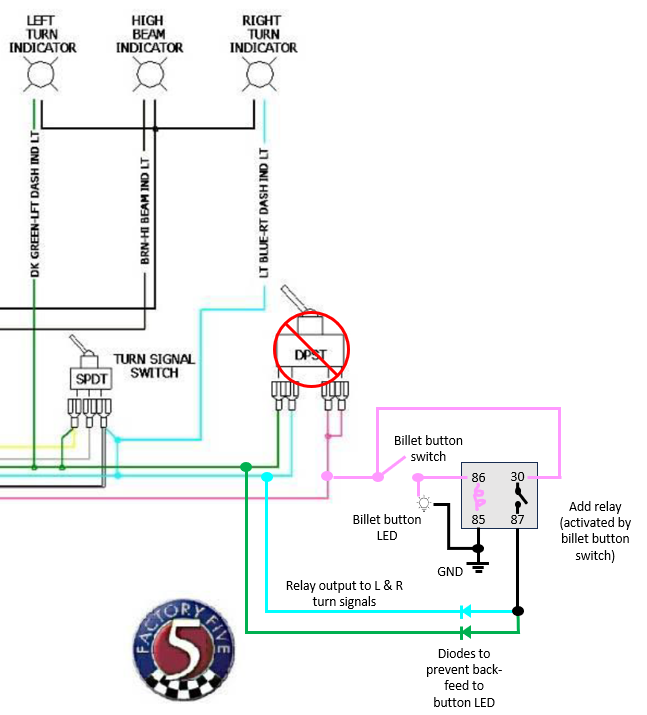
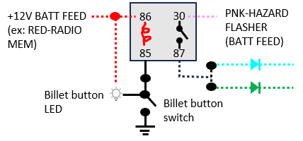
Another option would be to trigger the relay coil with any +12V BATT FEED source instead of using the PNK-HAZARD FLASHER feed. Could also move the button switch to the ground side of the relay coil (negative trigger). All this impacts is how the LED is wired. It would look like this --> not sure if there is any advantage to this vs. the option above. The primary difference is that using +12V battery feed vs. PNK-HAZARD FLASHER feed means the LED on the billet button will be fully illuminated while activated, vs. flashing with the hazards.
Last edited by dbo_texas; 01-12-2024 at 05:36 PM.
Reason: *edited diagram to LED tied to switched side of button
Darryl [dbo_texas]
MKIV #9644 (build thread) (Index)
MK4 Complete Kit | Gen2 crate Coyote | Tremec T56, 3.55 IRS | power steering | hydroboost | dual roll bars | FFR carbon fiber dash | 18" Halibrands + Wilwoods | RT drop trunk kit & turn signal | front battery mount | saddle leather Intatrim Stoneleigh seats + interior accents
-
Originally Posted by
dbo_texas
OK I "think" I have a handle on how I might need to wire the hazard switch (using Custom Billet Button). I want to use a relay (activated by the billet button) to turn on the hazard lights. I only want the hazard button to illuminate (and flash) when my hazards are on. I would use diodes on the output of the relay (direction flow going away from relay/button) to prevent back-feeding from the turn signal. I'm not sure in this setup if the diodes are really necessary because if the hazard button isn't pushed, then the relay contacts 30-87 are OPEN and no current could feed backwards anyway.
Can anyone confirm if my schematic looks like it would work? If there's an easier way to do this, I'm all ears. I've yet to find any clear diagram for how people wire up these billet buttons to the hazard switch (with relay). I have the pink 12V feed coming from the flasher on the fuse panel powering the billet button LED, controlling the relay trigger (positive), AND feeding the relay output to the L & R turn signals.
Are diodes really necessary with the way I have this wired up? If so, what size diode is appropriate for this application?
Another option would be to trigger the relay coil with any +12V BATT FEED source instead of using the PNK-HAZARD FLASHER feed. Could also move the button switch to the ground side of the relay coil (negative trigger). All this impacts is how the LED is wired. It would look like this --> not sure if there is any advantage to this vs. the option above. The primary difference is that using +12V battery feed vs. PNK-HAZARD FLASHER feed means the LED on the billet button will be fully illuminated while activated, vs. flashing with the hazards.
Pulling this one back up from a few months ago. Did you ever get your hazard momentary button wiring figured out, Darryl? I'm going with all Billet buttons (they look awesome - by the way!) but I'm still working through all of the connections. Funny enough, I'm using ie427's new column stalk, and with it came instructions on wiring his column switch to a DPDT relay for the hazards. I'm thinking of using those instructions to do something similar using my billet button. Screenshot below from ie427.
Capture.PNG
Also - I've found that customizing the buttons or dash options (in my case, using all Custom Billet buttons) has added a LOT (x5) of complexity to the electrical pieces of the build, for those of us who are not electrically-inclined. I'm slowly building a complete re-do of the wiring diagram, both for troubleshooting/documentation purposes and because I plan to share on the forum (work in progress below)...ya know....once it all works...hopefully. Just throwing it out there in case someone like me finds this in 6 months and it would be helpful to share.
Capture2.PNG


 Thanks:
  Likes:


 Reply With Quote
